Precision Machining for Space Components: An Instrumentation Guide
Key Takeaways:
- Precision machining for space components produces critical hardware for satellite instrumentation, including optical mounts, reaction wheels, waveguides and sensor housings.
- Material selection depends on weight, thermal expansion, outgassing, radiation exposure and the component’s operating environment.
- Tight tolerances, rotor balancing, specialty cleaning and controlled assembly help components meet their performance requirements.
- CMM inspection, material certifications and lot traceability help verify that parts meet engineering drawings and customer specifications.
- Space hardware buyers should evaluate suppliers on demonstrated capabilities, relevant certifications, in-house processes and experience with space programs.
A slight misalignment in a spacecraft’s optical mount can affect pointing accuracy. An imbalanced reaction wheel can introduce vibrations that interfere with sensitive measurements. In space, small manufacturing errors can have mission-wide consequences.
Precision machining for space components uses CNC processes to manufacture flight hardware to exacting dimensional, material and cleanliness requirements. For instrumentation, that means producing parts that position sensors accurately, minimize vibration and maintain reliable interfaces under extreme temperatures, launch loads and vacuum conditions.
What Is Precision Machining for Space Components?
Precision machining for space components uses subtractive CNC processes to manufacture hardware for satellites, spacecraft and launch vehicles. Applications range from reaction and momentum wheels to gyroscopes, star trackers, sun sensors, waveguides, RF housings, optical mounts and imager structures.
The distinction from general CNC machining is not necessarily the equipment. It is the level of control required over critical dimensions, material properties, cleanliness and documentation. A five-axis mill might machine both a conventional aerospace bracket and a star-tracker mount, but the fixturing, inspection requirements and handling procedures can differ significantly.
For instrumentation, those differences directly affect performance. The tighter the relationship between a component’s geometry and its function, the more important it becomes to control not just the final dimensions, but the entire manufacturing process.
Why Space Parts Need a Different Level of Precision
Space hardware is designed for conditions that ordinary industrial parts never see. The exact numbers depend on the orbit and the mission, but the pattern is consistent:
- Thermal swings. A spacecraft moves in and out of sunlight, and hardware can see temperatures ranging from roughly -150°C to +120°C.
- Vacuum. Ultra-high vacuum draws gases out of materials, and those gases can condense on optics and sensitive surfaces.
- Launch loads. Vibration and shock arrive across multiple axes at once, and every joint and bracket has to survive them.
- Radiation. Materials and electronics degrade over the mission.
- No serviceability. Once the spacecraft is up, nobody replaces a part. Missions can run 10 years or more.
Each constraint pushes the same way: tighter dimensional control, cleaner surfaces, and materials whose behaviour in vacuum and across temperature is known rather than assumed. A part that passes a dimensional check but outgasses in orbit can still ruin an optical payload. That is why space component machining is judged on the whole chain, not just the cut.
Space hardware must meet mission-specific mechanical, materials and cleanliness requirements. NASA-STD-6016 outlines requirements for materials and processes used in spacecraft flight hardware, while ISO 15388 addresses contamination control for spacecraft.
The European Space Agency’s mechanical engineering resources provide further context on the engineering challenges of designing hardware for launch and orbital conditions.
Materials Machined for Space Components
Material choice of space components is driven by mass, thermal expansion, outgassing behaviour, radiation tolerance and machinability. The common families and their typical roles include:
| Material | Typical use |
|---|---|
| Aluminum 6061-T6 and 7075-T6 | Structural panels, brackets, optical benches |
| Titanium Ti-6Al-4V | Pressure vessels, mounting brackets, propulsion structure |
| Stainless steels (300/400 series, 17-4 PH, 15-5 PH, Nitronic 60) | Fasteners, fluid system hardware, galling-resistant bushings |
| Nickel-based superalloys (Inconel 625/718) | Thruster components, high-temperature interfaces |
| Controlled-expansion and magnetic alloys (Kovar, HyMu80) | Optical benches, sensor mounts, magnetic shielding |
| Copper alloys | Waveguides, RF components, thermal management |
| Magnesium alloys | Lightweight structural and separation-system parts |
| Engineered plastics (PEEK, PTFE, Ultem) | Insulators, bushings, electrical parts; outgassing depends on grade, processing and qualification |
Where Instrumentation Tolerances Matter
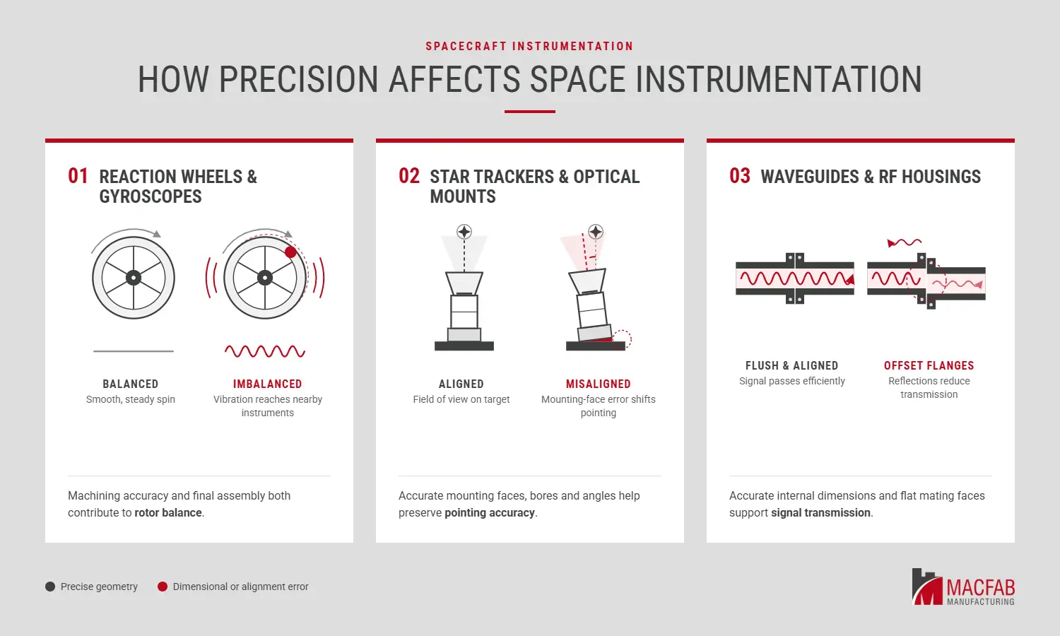
In spacecraft instrumentation, small dimensional errors can affect how accurately a sensor measures, how steadily a rotor spins or how efficiently a signal travels. The consequences depend on the component.
- Reaction wheels and gyroscopes: These rotating components must be carefully balanced. Even a small imbalance can cause vibrations that affect sensitive instruments elsewhere on the spacecraft. Machining accuracy and final assembly both contribute to the balance of the finished unit.
- Star trackers and optical mounts: These components rely on precise alignment. Errors in mounting faces, bores or angular positioning can shift a sensor’s field of view and affect pointing accuracy. Optical benches and mounts also need suitable surface finishes and protection from contamination, which can scatter light or obscure sensitive optics.
- Waveguides and RF housings: These components depend on accurate internal dimensions and properly aligned, flat mating surfaces. Poor alignment or surface irregularities can increase signal reflections and reduce transmission efficiency.
As small satellite and CubeSat programs pack more instruments into limited space and weight budgets, manufacturers must meet these requirements without adding unnecessary mass or complexity.
The Processes That Make Space-Grade Parts Possible
Space components require more than precise CNC machining. The manufacturing process may also include specialized balancing, cleaning, assembly and testing, depending on the part and its intended use.
Key processes include:
- Multi-axis machining: 3-, 4- and 5-axis milling, multi-axis turning, Swiss-style lathes and turn-mill machines produce complex geometries and precision features. Micro machining handles smaller features.
- Precision rotor balancing: Reaction wheel rotors and other rotating assemblies are measured for static and dynamic imbalance. Material is removed or added until the remaining imbalance meets the required limits at operating speed. Macfab’s precision rotor balancing capabilities support applications where vibration must be controlled.
- Specialty cleaning and cleanroom assembly: Parts are cleaned to remove machining oils, residues and particulates that could contaminate sensitive hardware or contribute to outgassing in vacuum. Cleaned components can then move into a cleanroom for sub-assembly and final assembly.
- Helium leak testing: Pressure- and vacuum-critical components can be tested using mass spectrometry to detect leaks. Macfab’s helium leak testing takes place before cleanroom assembly when the test requirements and process sequence call for it.
Keeping precision machining and supporting processes with one supplier can reduce handoffs between operations and simplify coordination.
These processes help meet flight acceptance and qualification requirements, but they do not replace them. Final verification depends on the mission, customer specifications and applicable program requirements.
Tolerances, Quality and Traceability
For space work, Macfab holds critical features to ±0.0025 mm (±2.5 microns) and verifies them using coordinate measuring machine (CMM) inspection on every lot. Its manufacturing processes operate under AS9100 and ISO 9001:2015 certifications.
The drawing and the component’s function determine the tolerances needed. Tighter tolerances can add cost and production time, so they should reflect actual performance requirements.
Traceability starts with the material and continues through manufacturing and inspection. Mill certificates document material properties, while inspection records show whether finished parts meet the drawing.
First-article inspection verifies the manufacturing process before serial production begins. CMM inspection checks critical dimensions, and on-machine measurement can help identify dimensional drift during machining, before it affects more parts.
For controlled or export-controlled projects, buyers should also confirm the applicable registration, access and handling requirements with their supplier. These depend on the program and the parts involved.
How to Choose a Space Machining Partner
The right supplier should be able to demonstrate its capabilities, quality controls and experience with space components. Here’s a simple checklist to get started:
- Certifications. Look for suppliers with AS9100 and ISO 9001:2015 certifications. Ask for their certificates and scope, then confirm which certifications your program requires.
- In-house integration. Ask whether the supplier handles cleaning, cleanroom work, testing and balancing in-house. Keeping these processes together reduces handoffs and limits opportunities for contamination or handling damage.
- Demonstrated tolerances. Ask which tolerances the supplier can consistently hold on critical features and how its inspection process verifies them.
- Space program experience. Review the supplier’s experience with actual space projects, not just its capability list. For example, Macfab has worked with the University of Toronto Institute for Aerospace Studies on micro- and nanosatellite programs.
- Prototype to production. Choose a supplier that can carry a part from CNC prototyping into production using consistent processes, without losing knowledge or introducing unnecessary delays during the transition.
Frequently Asked Questions
What Tolerances Do Space Components Need?
It depends on the part and the program. Critical features can sit in the micron range, while non-critical features are much looser. Macfab holds ±0.0025 mm on critical features and verifies them by CMM, but the drawing and the mission set the requirement. Tolerances should reflect each feature’s functional requirements. Tighter tolerances can increase manufacturing costs and production time, so specify them where they’re needed to meet performance requirements.
What Materials Are Used for Space Components?
Space components can use aluminum alloys, titanium, stainless steel, nickel-based superalloys, copper alloys, controlled-expansion alloys and engineered plastics. Each serves different needs. Aluminum helps reduce weight, titanium combines low weight with high strength, and nickel-based superalloys suit applications that require high-temperature performance. Copper alloys support electrical and thermal applications, while controlled-expansion alloys help maintain dimensional stability as temperatures change. Engineers select materials based on the component’s function, weight limits, thermal conditions, outgassing requirements and machinability.
Can One Supplier Machine, Clean and Assemble Space Hardware?
Yes, when the supplier owns those steps. Keeping machining, cleaning, cleanroom assembly, leak testing and balancing under one roof reduces handling and protects cleanliness between steps. Macfab runs that chain in-house, which is unique among contract machine shops.
How Are Space Components Tested Before Flight?
Space components undergo inspections and tests based on their function and mission requirements. These may include coordinate measuring machine (CMM) inspections to verify critical dimensions, first-article inspections to confirm the manufacturing process, and checks of material certifications and process records. Manufacturers may also perform cleanliness inspections and leak testing on components that must contain pressurized fluids or maintain a vacuum seal. The customer and supplier establish the required inspections and acceptance criteria before production begins.
Getting Space Components Ready for Production
If you are sourcing instrumentation hardware and want a manufacturability review before quoting, Macfab’s technical team can look at the drawings and the tolerances with you. Request a quote or speak with a Macfab expert.
